Assembly instructuins triflex® RSP - pull-back system
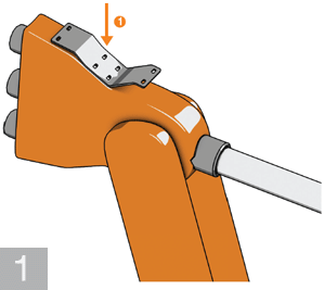
Assemble adapter plate (1) onto axis 3 of the robot
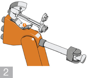
Assemble the igus® RSP system directly onto
a) the adapter plate (1) or
b) directly onto your robot if an adapter plate is not needed.
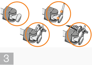
Assemble the "clamp clip" (2) on axis 6 of the robot and then the adjustable triflex® R mounting bracket
onto axis (3)
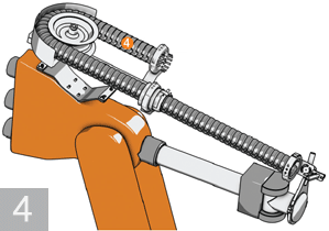
Place your triflex® R e-chain® into the RSP system (4)
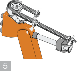
Adjust the length of the triflex® R chain and secure
the chain on the fixed end of the RSP system and on the moving end
mounting bracket of axis 6
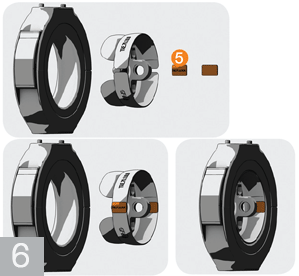
only applicable to triflex® TRE:When fastening the mounting brackets, note that the part TRE.Lock (5) must be inserted into the last chain link on the fixed end and the moving end of the triflex® TRE.
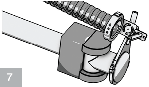
Align the clamping clip on axis 6 and the pivot bracket with mounting bracket in such a way
that the triflex® R is positioned ideally. The ideal
position and chain length are determined
by the robot program
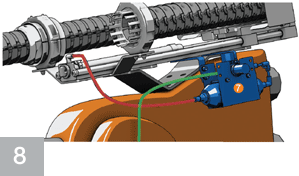
Connecting the pressure compensator (7)
Use the supplied 1m hose (marked red) to connect the RSP unit to the pressure reservoir. The fitting on the pressure
valve is connected to the on-site compressed air system
(marked green).
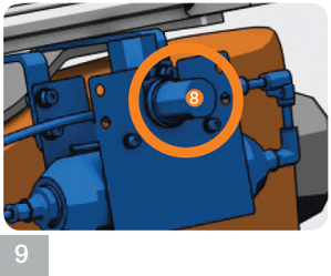
Adjust air pressure using the pressure regulator (8)
The correct pressure is between 2 bar (29 PSI)
and 4 bar (87 PSI)
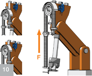
The ideal retraction force adjustment is made by filling the triflex® R with cables and hoses and by guiding the robot downward with axis 6 in a vertical position. Increase the air pressure using the pressure regulator such that
the e-chain® is lifted completely and the cylinder
reaches the limit position. This adjustment then corresponds to the maximum required retraction force.
More than 100,000 products available! Delivery and consultation Mon-Fri from 7am-8pm and Sat from 8am-12pm!