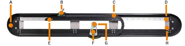
A = Simple, quick assembly | B = Circumferential moving end: Energy, data, media
C = Proven igus® e-chain® | D = Light, stable guidance
E = Support of the long travels | F = Fixed end = rotary feedthrough
G = Optional with Chainflex® cables | H = Variable length through modular design
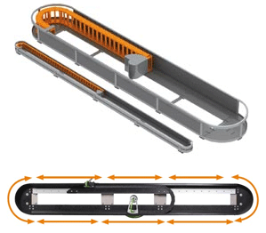
c-chain modular kit: Many possibilities all around
Continuously revolving energy supply system made of standardized modular components. New perspectives emerge due to avoidance of unused down journeys.
Application areas
Handling systems
Filling and discharge equipment
Feeder
Pick and Place
Bonding systems
Portal
"Intelligent" conveyor belts and transport systems
Stacking, sorting, palettizing
Advantages:
Compact modular system ready to install
Energy guide plus BUS cable and pneumatic
Speeds up to 3 m/s
Travel length up to 50 m
Versions available:
The c-chain module range for the e-chain® E4.21.050.075.0 is available from stock. All other sizes have a delivery time of 4 weeks.
e-chains® for the c-chain® module kit
| Series | |
|---|---|
| E4.21.050.075.0 |  Inquiry Inquiry |
| E4.21.080.200.0 | Inquiry |
| E4.28.075.200.0 | Inquiry |
| E4.32.07.200.0 | Inquiry |
| E4.42.06.300.0 | Inquiry |
| E4.42.15.300.0 | Inquiry |
| E4.56.13.300.0 | Inquiry |
| E4.56.26.300.0 | Inquiry |
| E4.80.12.300.0 | Inquiry |
| E4.80.26.300.0 | Inquiry |
| E4.80.26.400.0 | Inquiry |
connectors:
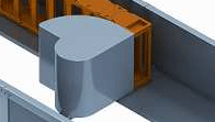
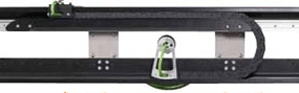
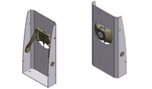
In a c-chain®, the e-chain® rotates at the fixed end with the rotary feedthrough. The fixed end rotating arm guides the e-chain® and supports it during the deflection of the rotary feedthrough, which prevents too high tensile forces in sharp edges. It is manufactured to match the rotary feedthrough and e-chain®.
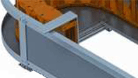
An L-angle is integrated in the c-chain module, which is attached to the mounting bracket (see picture), so that the customer can attach his moving end to the c-chain as easily as possible.

Optional - aluminum section integrated in the trough brackets, for a simpler installation.
Long unsupported lengths:
In long unsupported travels the upper run of the e-chain® has to be supported, which prevents the e-chain® from sagging and thereby increases the service life of the system.
Solution 1:
The first solution is a glide bar guided by a linear guide. The upper run of the e-chain® can rest on that. Here the e-chain® pushes the glide bar in front of it, thereby placing the bar always in the right position.
Solution 2:
The second solution uses the horizontal guidelok system to support the upper run. Thereby the moving end guides the e-chain® above the supports. The e-chain® can be laid, while the radius can push the rollers to the side. This solution has so far achieved the highest side-mounted standing system length of 30 m.
Rotary unions:
Almost all kinds of electricity, data, air or liquids can be carried in the c-chain® with a rotary feedthrough to the e-chain®. Each combination of these media results in a different rotary feedthrough. igus® would be happy to assist you in designing and ordering the appropriate rotary feedthrough.
Max. travels and loads
The maximum travel with a c-chain is 50 m in horizontal application and 30 m in side-mounted standing application. The maximum speed is 3 m/s and the maximum acceleration is 30 m/s².
material
The used e-chains® are made of black igumid GLW. The trough parts are made of black powder-coated steel with a gliding pad made of HDPE.
More information:
Downloads:
More than 100,000 products available! Delivery and consultation Mon-Fri from 7am-8pm and Sat from 8am-12pm!