igus® LeviChain - Almost contactless energy supply system for long travel distances
The principle of the magnetic "floatation" is based on the attractive forces of the prevailing magnetic field, which "centers" the E-Chain® in all directions. By this "centering" the E-Chain® moves almost contactless with favorable friction and wear behavior and minimum abrasion.
Long travel distances possible, without laying the
E-Chains® on top of each other
Almost no abrasion and "no" wear due to low-abrasion E-Chain® links (without pin/hole connection) as well as almost contactless movement of the energy chain
Compared to other energy supply systems, the igus® system LeviChain is extraordinarily low noise [41.7 dB(A) in 1 m distance], as there is almost no rolling or grinding noise
High speeds and accelerations, as well as braking action possible
Simple assembly, also in installed condition with cables and hoses through the proven "Easy" principle
Variable installation positions (horizontal and vertical) possible
Little space requirement in height and width
IPA certificate
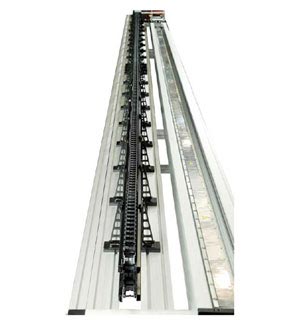
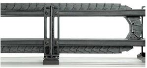
Long travel distances up to 40 m with high speeds and accelerations, almost without contact, possible with the new igus® LeviChain
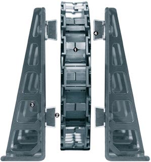
Modular igus® E-Chain® in various widths and bending radii, "magnet-free"
2Contactless guidance in the top run and alternatively in the bottom run too
3Support elements
4Magnet modules
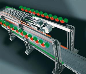
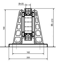
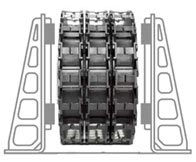
LeviChain principle - Schematic diagram of the magnetic forces

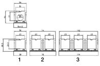
1 Horizontal applications
2 Suspended applications
3 Standing applications
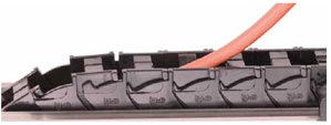
Simple insertion of cables through the proven and tested "Easy" design

2 E-Chains® attached in opposite directions

Offset movement possible
Clean rooms
Paint operations/shops
Medical technology
Measuring technology
Electronic manufacturing
Rack conveying equipment / material handling
Industrial robots

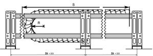
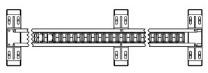
Min. travel S 1000mm; in 25 mm steps
Magnet modules:
M: Magnetmodule
B: Support tray
MM: Magnet modules above/below
MB:Magnet modules above, Support trays below
Optional arrangement
RL = E-Chain® counter run (E-Chain® right and left)
Order example: LV.25.3/25.125.1500.MM
LV = igus® LeviChain system
25 = Inner height Hi
3 = 3-profile design
25 = Inner width Bi
125 = Bending radius
1500 = Travel distance
MM = Magnetic module top/bottom
| available bending radii for 1-, 2- and 3-band [mm] | ||||||
|---|---|---|---|---|---|---|
| 045 | 063 | 075 | 100 | Max. fill weight | 4 kg/m | |
| 125 | 150 | 175 | 200 | Max. travel | 40 m | |
More than 100,000 products available! Delivery and consultation Mon-Fri from 7am-8pm and Sat from 8am-12pm!
 Inquiry