Example 5: Dispersion and attenuation

Plastic fiber-optic cables have been introduced for data
transmission in industrial applications due to their excellent
interference-proof properties against electro-magnetic fields
and further advantages such as the possibility of reducing
dimensions and weights. The application as flexible link
lines particularly in Energy supply chains places high
demands on plastic fiber-optic cables.
The most important characteristic values of a fiber-optic
cable are dispersion and attenuation. Dispersion is the term
used to describe the scattering of the travel time of the signal
in the fiber-optic cable. In plastic fiber-optic cables this is
essentially caused by the mode dispersion, which arises
from the different travel times of individual light beams.
Dispersion determines important transmission properties
such as bandwidth, cut-off frequency or maximum bit rate.
Significant changes in dispersion could not be ascertained
in any of the investigations carried out.
The industrial application of igus Chainflex®-lines with plastic
fiber-optic cables in supply chains for example is therefore
unproblematic with regard to changes in dispersion.
The second important characteristic property, attenuation,
determines the maximum possible length of a transmission
path.
The attenuation of a plastic fiber, like that of the glass fiber,
is also strongly dependent on the wavelength of the light
used. For this reason all the investigations were carried out
with a wavelength of 666nm.
Depending on the output of the transmitter and the sensitivity
of the receiver the operator has a certain "attenuation
budget" available for the complete transmission path
including all junction and transition regions. This attenuation
budget (typical value approx. 20dB) must not be exceeded
if a secure transmission of the data is to be guaranteed.
For this reason it is of great interest to the user to know
whether and to what extent increases in attenuation are to
be expected for his particular application so that these can
be taken into account in the compilation of his own attenuation
budget.
In addition to continuous bending stress, which is typical
for operation in an Energy chain, further mechanical stresses
that can occur during installation or operation must be taken
into account. Thus, for example, relatively large tensile forces
can occur when integrating the line into an Energy chain.
The fixing of the lines at the ends of the energy chain using
cable clamps leads to permanent transverse loads.
The test of the behaviour under transverse load is carried
out following DIN VDE 0472, Part 223. Since the cable
clamps only exercise pressure in an area covering a few
centimetres, increases in attenuation are relatively low.
Attenuation under tensile load depends to a great extent
of course on the composition of the line. Lines with integrated
copper conductors or strain relief elements do not
reveal a noticeable increase in attenuation until very much
greater tensile forces are applied than is the case with pure
fiber-optic cables.

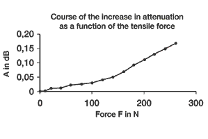
Figure 1 represents test results for a Chainflex®-line with 6 fiber-optic cables. The length of the test sample is 1m and the maximum tensile load 250N.

The tensile forces required to integrate fiber-optic cables in Energy Chains® are usually much lower than 250N. The increase in attenuation was 0.17dB at maximum tensile force and disappeared completely after the tensile load was released. Thus no effect on attenuation should be expected. In the case of plastic fiber-optic cables that are bent very often, as is the case in applications with Energy Chains®, then further influencing factors such as material fatigue, dulling of the materials, micro-cracks right through to complete fiber fracture must be feared, and their influence on attenuation can only be investigated in extensive practical tests such as those carried out by igus®. Figure 2: Course of the increase in attenuation as a function of the number of cycles.
The excellent test results, shown in part here, of the Chainflex® -lines must not be taken for granted, as investigations of fiber-optic cables from other manufacturers showed, some of which even failed with complete breaks in the fibers. The investigations revealed that Chainflex® fiber-optic cables are not influenced in their function by mechanical loads such as tensile, transverse or bending stresses in Energy Chains®. Therefore they are perfectly suitable for use in the sometimes rough industrial environments for the interference- proof transfer of information between drive and control elements of machines.
More than 100,000 products available! Delivery and consultation Mon-Fri from 7am-8pm and Sat from 8am-12pm!