DryLin® N - Low profile linear guide system NK-22-17-40
)
DryLin® N low profile guide system rail
| Order no. | Max. rail lengths | a | C4 | A3 | C5=C6 | h | h1 | K1* | ly | lz | Weight of rail | Price / m | ||
|---|---|---|---|---|---|---|---|---|---|---|---|---|---|---|
| [L max.] | Min. | max. | [mm2] | [mm2] | [g/m] | |||||||||
 NS-01-17 NS-01-17 |
2000 | 17 | 60 | 0 | 20 | 49,5 | 5.5 | 0.9 | M3 | 1700 | 120 | 150 | 38.99 USD |  |
| More about selected part: | ||||||||||||||
3D-CAD Sample request
Experts
PDF
Quote request
Price list
myCatalog
Sample request
Experts
PDF
Quote request
Price list
myCatalog
|
||||||||||||||
* for cylinder screw with low head
Drylin® low profile linear guide system NK-02-17
| Order no. | Designation | Weight of carriage | ||
|---|---|---|---|---|
| [g] | ||||
| NW-22-17-40 |
Double carriage with threaded bore | 2.6 | Upon request | |
| NW-22-17-40, LLY |
Double carriage with threaded bore floating bearing y-direction | 2.6 | Upon request | |
| NW-22-17-40, LLYZ |
Double carriage with threaded bore floating bearing y- and z-direction | 2.6 | Upon request | |
| NW-22-17-40, LLZ |
Double carriage with threaded pin, floating bearing z-direction | 2.6 | Upon request | |
| More about selected part: | ||||
|
3D-CAD
Sample request
Experts
PDF
Quote request
Price list
myCatalog
|
||||
Dimensions [mm] - guide carriages
| Part. No. | H | A | C | C1 | C2 | A2 | H2 | K2 | K3 | K4 | Sp min. | Dp Ø min. | Weight |
|---|---|---|---|---|---|---|---|---|---|---|---|---|---|
| ±0,35 | [g/m] | ||||||||||||
| NW-22-17-40 |
6 | 9.6 | 40 | 40 | 28 | 0 | 0 | - | M3 | - | 2.5 | 5 | 2.6 |
| NW-22-17-40, LLY |
6 | 9.6 | 40 | 40 | 28 | 0 | 0 | - | M3 | - | 2.5 | 5 | 2.6 |
| NW-22-17-40, LLYZ |
6 | 9.6 | 40 | 40 | 28 | 0 | 0 | - | M3 | - | 2.5 | 5 | 2.6 |
| NW-22-17-40, LLZ |
6 | 9.6 | 40 | 40 | 28 | 0 | 0 | - | M3 | - | 2.5 | 5 | 2.6 |
| More about selected part: | |||||||||||||
|
3D-CAD
Sample request
Experts
PDF
Quote request
Price list
myCatalog
|
|||||||||||||
Ordering of a complete system
Configuration in few steps:
1. Selection of the number of carriages
2. Selection of the type of carriage
3. Entry of the rail length in mm
4. Selection of the carriage options
5. Selection of the rails options.
Hint:
Detailed information can be found below in the drawings as well as in the below-mentioned pages. You can obtain precise specifications on the floating bearing options within the design rules.
1
no floating bearing
2Floating bearing in z-direction
3Floating bearing in y-direction
4Floating bearing in yz-direction
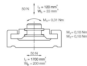
Static load capacity and moments of inertia of an area
A =bore min. Ø 5 mm
B = Depth for screw tightening
C = for machine screws M3
DIN 7984/DIN 6912/DIN 84
EN ISO 1707
More than 100,000 products available! Delivery and consultation Mon-Fri from 7am-8pm and Sat from 8am-12pm!