Leo 09
Performance and functional description of Leo 09The first image shows an overall view of the Leo 09 as a 3D illustration. To ensure that the directions of travel are uniformly named, direction descriptions were inserted in the picture.
The robot consists of 5 key components that are required to master its tasks
1. Drive
2. Rotary storage device for receiving and storing the pucks
3. Horizontal transport system 1 to remove the pucks from the rotary storage device
4. Horizontal transport system 2 to push the pucks out of the robot
5. Vertical transport system to lift the pucks to build the towers
A puck taken from the rotary storage device goes through components 3 and 4 in sequence until discharged and is raised to a required level if necessary with component 5. A detailed description of the individual components follows.
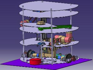
Image 1-1 Definition of the direction description relative to the robot
)
The drive system is used to move the robot to the required place on the playing field. This includes the devices for determining its position and controls in the form of the odometry system.
The rotational storage device is used to remove the pucks from the dispenser, store them and make them available at the appropriate place to be transported further in the robot. The rotational storage device is driven by direct current motor via a shaft and a toothed belt. In order to be able to set any given angle position, an absolute encoder is connected to the shaft on the rotation storage device.
The rotational storage device consists of two disks. A bottom disk and a top disk. Both disks cannot twist against each other. Three slots are incorporated into the top disk. The pucks can be picked up into these slots. There is only one slot in the bottom disk, which is fitted directly below one of the slots in the top disk. That results in a storage place with no base. This place is required to be able to move to the dispenser filled with pucks. In Image 1-3 the rotational storage device can be seen in the puck receiving position.
When the Leo 09 has moved up to the dispenser, the pucks can be accommodated in the two remaining slots one after the other by means of the storage device rotating. Besides the puck receiving position, there are two other notable positions for the rotational storage device, the puck release positions. These are illustrated in Image 1-4. They are reached by the rotational storage device rotating anti-clockwise. Only those pucks that are in slots with a base can be taken back out of the rotational storage device.
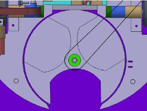
Image 1-3 top view of rotational storage device – puck receiving position
)
On the outside of the rotational storage device is a tactile sensor (micro switch). When the storage device rotates, this is activated if there is a puck in a slot. Combined with the absolute encoder, it can be used to check whether a puck has been received in the corresponding slot.
The puck, which has been received in the slot without a base, cannot be transported outside via the horizontal and vertical transport system. It remains in the rotational storage device and must be either left at the dispenser or can be taken with the robot and then only installed in building zone 1. To transport the puck, the rotational storage device must adopt one of the two positions shown in Image 1-4 whilst moving.
The horizontal transport system 1 has the task of pushing the pucks out of the rotational storage device that are in a release position (see Image 1-4) and moving them to the transfer position, from where the horizontal transport system 2 or the vertical transport system takes over the job of transporting the pucks further.
The horizontal transport system 1 pushes the puck out of the rotational storage device across a ramp using a pusher fastened to a slide. The pusher pushes the puck until a limit switch (micro switch) is activated and the horizontal transport system 1 stops. The puck now rests on the lifting platform, which is fastened to the vertical transport system.
The horizontal transport system 1 can be moved back into its starting position. In this case the pusher is moved until a limit switch is activated again.
The horizontal transport system 2 now has the task of transporting the puck backwards on the lifting platform with the aid of the moving end (see Image 1-5 and Image 1-6). There are 3 different positions which can be moved to by the horizontal transport system 2
1. Position where the puck is transferred from h. transport system 1
2. Interim position, to push the puck a bit further backwards, to make room for the next puck from the rotational storage device
3. End position, is moved to in order to push the puck out of the robot
Reaching the positions is signaled in each case by the activation of a micro switch.
)
)
With the help of the vertical transport system, the pucks pushed onto the lifting platform by the horizontal transport system 1 can be moved upwards in order to stack pucks on top of each other or to reach higher building zones.
A micro switch is used to check whether the vertical transport system has reached the required height. The switch is fastened directly on the lifting platform as seen in Image 1-8 and moves up and down with it. Screws fastened on a rail can be placed on the required levels, where they activate the micro switch.
)
)
Another function of the vertical transport system is to transport the cross-pieces (lintels) and set them down on build up towers and if necessary fetch new pieces from their storage places.
The lifting platform can be moved up 160 mm in total. With a puck height of 30 mm, a maximum of 5 pucks can therefore be stacked on top of each other.
To detect whether there is already a puck in a place where a tower is supposed to be built, the ejection area can be checked with the aid of two distance sensors. Beam angle and direction of the distance sensors are illustrated in Image 1-10. As the sensors are able to move up and down with the lifting platform, it enables this system to also make out the top edge of a tower, in order to be able to stack another puck on it.
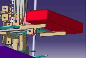
Image 1-9 Transporting a lintel
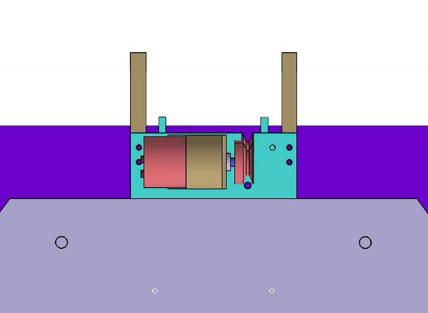
Image 1-10 Beam angle and direction of the distance sensors to check the building zones
To be able to receive the maximum number of 4 pucks, reception must take place in two phases.
In the first phase the two storage spaces with bases are filled with one puck each. The rotational storage device is rotated as far as release position 1 and stopped. The puck is taken out of the rotational storage device using the horizontal transport system. If the slot is empty, the dispenser is rotated further again in the second phase and the next puck in the dispenser drops into the slot that has become available.
The Leo thus has one puck on the lifting platform, two in the storage device, which is can push out backwards, and one resting in the slot without a base.
For moving up to the dispenser, the Leo must align itself so that it can move forwards up to the dispenser at a 90° angle to the side cushion. The rotational storage device has adopted the puck receiving position (see Image 1-3).
The Leo moves until the dispenser is enclosed by the recess intended for it (see Image 3-1). So that the Leo detects whether it has moved closed enough to the dispenser, there is a micro switch in the recess, which is activated by the outer shell of the dispenser.
)
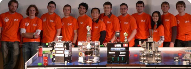
The Leo 09 should be able to be exhibit the following capabilities in play. The points in bold have priority. It can
1. in one go take 4 pucks out of a dispenser filled with 5 pucks (one of the 4 pucks may only be received in a way that makes it unable to be released via the horizontal and vertical transport systems)
2. build towers on each of the three building zones
3. build a temple with the 4 pucks from one dispenser emptying process
4. if the slot without a base is empty in the rotational storage device, pick up a puck from the playing field and install it in building zone 1