Gliding - long travels

Advantages for long travel applications with igus® E-Chains®

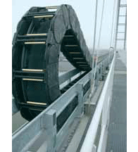
Travels over 600 m

Surface speeds up to 6 m / s (up to 10 m/s possible in consultation with igus®)

Fill weights up to 70 kg/m

Service life of 10 years and more with igus® energy chain systems®


Further advantages of the design are:

Many different types of cables and hoses can operate side by side in the same system (i.e. electrical, data, fibre-optic cables with hydraulic and pneumatic hoses)

Compact installation

quieter motion

Capable of withstanding high accelerations

Resistance to wind, weather, dirt and chemicals

Easy assembly of modular systems on location

Quick assembly and upgrading of cables
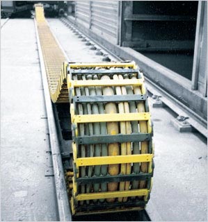
Long travels. For example: Conveyor system in stone quarry, travel 179 m, speed 67 m/min, fill weight 8 kg/m


Gliding application:

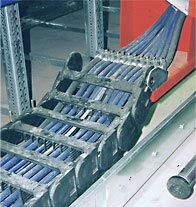
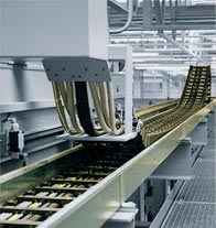
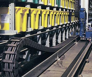
If the upper run of the E-Chain® rests on the lower run, it is a gliding application


Over 600 m travel

6 m/s speed

Fill weights up to 70 kg/m

 
Design assistance, free of charge

We recommend that igus® calculate every gliding application for you. We will always offer the most costeffective solution, taking the technical requirements and operating safety into consideration.

To be able to advise you accurately, we require the following specifications:

Travel [m]

Travel speed [m/min] or [m/s]

Acceleration [m/s²] 2]

Fill weight [kg/m]

Maximum cable/hose outer diameter [mm]

Type and number of cables and hoses

Required bending radius [mm]

Cycle frequency (n/day or n/hour)

Technical environment

The world's longest igus® travel of 615 m with e-chains® and chainflex® cables

 
Please call us and within hours you will receive a detailed system proposal!

Trends in long travel applications

Long travel with the world's largest e-chain® - Series E4.350

 
Very long travels with igus Rol E-Chain. - Rolling instead of gliding:

75% less push-/pull forces due to special roller-links. Travels up to 800 m are possible. At present the longest igus® travel path of 615 m is implemented with igus® rol e-chain® and chainflex® cables

Long travels without guide troughts:

Our AUTO-GLIDE system consists of self-guiding e-chains® for travels up to 50m travel lenghts (speed 1,5m/s) due to special gliding elements on the crossbars. The installation and the material for the otherwise essential guide trough are not applicable

Long travel "on a roll": Up to 100 m travel-
path preassembled

 
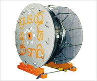
Long travel "off the reel."

Complete costum-made e-chainsystems® with cables, connectors, strain relief - are delivered on the reel and "rolled off" into the preassembled Guide Troughs. Time savings of 50% possible.

Long travels with small e-chain®:

The micro flizz® system offers the potential to safely guide power, data and media in a small e-chain® with high acceleration in long travels. The components are protected against dirt and weathering and operate absolutely free of maintenance.

World's largest polymer e-chain®: many times lighter than comparable steel chains, it effortlessly moves a fill weight of more than 100 kg per metre on a travel of 138 m.


Preferred E-Chain® - gliding, long travel
The gliding application system of igus® E-Chain®

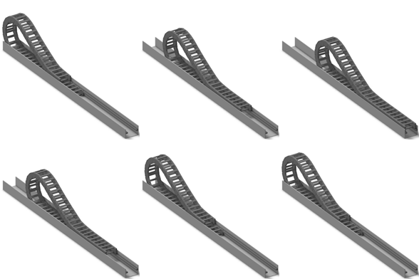
In long travels the upper run of the igus® e-chain® is placed on the lower run. The upper run glides partly on the lower run and partly on a glide rail at the same height. The graphics below show this principle. A trough is required for lateral guiding. If the fixed connection and the feeding of the cables can be carried out in the middle, the chain length is calculated as follows: Length of e-chain®: Lk = S/2 + K2. Depending on the technical data and the selected e-chain®, the connection point of the moving end of the e-chain® must be set lower (lowered moving end) in some units.
 
In our system analysis for long travels, we give exact details for your specific application.

Example of lowered mounting height


Advantages lowered moving end:

Space saving

Longer travels possible

Higher service life due to less wear


Gliding applications = Pivoting mounting brackets

A1 = guide trough with glide rail
A2 = guide trough without glide rail
A3 = total length of guide trough
∆-CL = offset fixed point
The schematic functioning of an e-chainsystem® in a gliding application. The fixed end of the e-chain® is located in the center of the travel distance


A total length of guide trough
Solution with two oppositely arranged e-chains®. The complete travel is arranged thus.
Application in crowded spaces and high loads

 
E-Chain® length:
Lk = S/2 + K

S = travel
R = bending radius
∆CL = offset fixed point
HRi = trough inner height
HF = required installation height
K2 = further addition, if connection point is lowered (will be stated by us)
K = R * p + (2 x T)
(please find K from the dimension sheets of the individual igus® series)
D2 = projection on long travel distances gliding

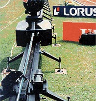
Mobile camera, Olympic Games in Atlanta, S = 100 m, v = 10 m/s in push-pull operation


Robotics: quiet running, high acceleration. Up to 10.000 cycles per day

 
Guide troughs

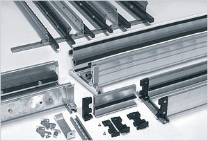
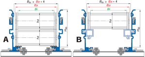
Due to the guide troughs, the e-chains® and e-tubes from igus® can continue to run quietly and with low friction in long travels. Unifilar drawings can be found on this page. The height of the guide trough must as a rule be equal to at least double the chain height. The sides must provide a chamfered opening. The trough inner width is equal to the outer chain width plus 4 mm (in super aluminium guide troughs)BRi = Ba + 4.Along the side of the trough, where the upper run cannot glide on the lower run, glide bars must be installed. We recommend the use of plastic glide rails from the igus® range. They are optimally matched to the e-chain® material and achieve the lowest values for friction, noise and wear. Guide More application examples for long travels www.igus.de Gliding long travels troughs with or without glide rails are available for almost all igus® e-chains® from stock.

Important: When assembling the trough parts, the following points must be given particular attention:

Properly align all trough parts upon installation

All screw heads should be flush with the trough

Smooth levelled transition between the end of the E-Chain® and the glide bars

Solid connection with the glide surface. These points must be observed when using assembly-friendly igus® guide troughs.

If the fixed point is in the center of the travel, use half of the guide trough with glide bars and the other half of the guide trough without glide bars


A: Guide trough without guide rail - upper run glides on the lower run
B: Guide trough with glide rails. Upper run glides from the half of the travel on the glide rail. We recommend the use of plastic glide rails from igus® made of igulen. They are perfectly matched to the material of the e-chain® and achieve the lowest values in terms of friction, noise and wear.


Ba = Chain link width outer
ha = Chain link height outer
HRi = Trough inner height
BRi = Trough inner width
HRi ≥ 2 * ha
BRi ≥ Ba + ≈ 5 mm


Guide troughs are used for long travels. They allow igus® EChain® and E-Tubes to continue smooth, low-friction operation in these long-travel situations. Various guide troughsystems are available

Coefficient of gliding friction for igus® e-chains® made of igumid G / GLW and various glide rails

igumid G/GLW igus® polymer
bar igulen
Glide
sheet steel
Anodized
aluminum
Stainless steel
Friction value - dynamic 0,19 0,45 0,54 0,48
Source: igus® laboratory

Travel speeds and accelerations

Travel speeds up to 5 m/s in continuous operation are possible and in use on current applications. Even higher speeds are possible in special cases. In crash test facilities, for example, E4 system e-chains® reach speeds
of 22 m/s and accelerations of 784 m/s2
. However, only a few thousand cycles are required per year. Acceleration plays a large role in the calculation. A distinction is made between the normal operating acceleration and a sudden, jerky acceleration, as well as unexpected stops or the so-called "e-stops". Even in these situations, igus® e-chains® prove to be very durable. The correct design by our technicians is a prerequisite.

Service life

We offer service life calculations for your application based on our extensive gliding application experience. As developers of polymer plain bearings, we possess vast material behavior knowledge which we apply to the development of E-Chains® as well. Units with 200 m travels have been in operation for 8 years with minimum maintenance. Units up to 60 m travels have been in operation for 12 years with almost no maintenance. Please consult igus® for references and calculations for your project. The maintenance-free aspects of igus® EChainSystems® over long periods and under rough operating conditions is often the deciding factor in choosing igus®. Our system guarantee (depends on the application) provides additional peace of mind.

Special properties - Long travel applications

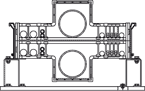
E-Chains® that are nested can be used in gliding applications. This type of installation is most often used when there is a width restriction. Guide troughs with special wall heights are necessary. E-Chains® running side by side, or in a "multiband" design can also be used in gliding applications. Higher fill weights often require special guide troughs which can be delivered either from stock or on short notice. Higher fill weights are often a reason for this solution. We have also developed standard parts for unconventional solutions involving large hoses in gliding applications. We have developed standard parts for this purpose, which we'd be glad to offer you on request.

Technical environment

Long travel applications using igus® Energy Chains® run in water, in dirt, in the tropics, in explosion risk areas (with special design features) and many other conditions. You will find more details in the Technical Environment section of this chapter. Guide troughs can be supplied in corrosionfree materials.

Calculation

Comprehensive tests place us in the position of knowing our products precisely. Important factors in these tests are:

Push-pull forces under both ambient and extreme temperatures. Humidity and dirt.

Friction values of the polymers, alone and against various glide surfaces

Behavior of electrical conduits under push-pull conditions

Behavior of hydraulic and media hoses under pushpull conditions

Service life, and noise generation.


If we cannot in fact calculate your application based on these factors, we will perform a practical test for you in our laboratory. Please consult igus®.

Corrosion-free guide troughs are available in the material:

Normally galvanized

Stainless steel

Seawater resistant aluminum

Automated storage/retrieval system with System E2 and Chainflex® cables - travels up to 80 m and speed of 4,5 m/s


Series 38 in a pre-cast concrete plant with dust and concrete sediment


Large hose elements


Technical data - long travels

Travel max. 600 m - 800 m
Travel speed max 10 m/s
Travel acceleration max dependent on calculation,
can be 50 m/s² and more
Fill weight max. Depending on the calculation,
can be 70 kg/m and more

PPDS status monitoring
PPDS - Push Pull Force Detection System

The PPDS system is an electronic diagnostic tool that monitors the displacement forces of energy chains online to prevent damage to the system as well as failures. Too much dirt, ice and snow or falling debris can block the system, thus leading to a rise of the chain and a breakage of the e-chain®. Several times per second, the PPDS system measures the displacement forces of the e-chain® and compares the data with the calculated nominal value. In case of deviation, the system can be automatically stopped by means of the PPDS. 3 igus® PPDS systems are at your disposal:

PPDS basic

PPDS advanced

PPDS pro

 
Product benefits

Easy installation by means of non-interchangeable connectors

Easy programming using the membrane keypad directly on the unit

Compact housing, stable, corrosion-resistant, sealed in accordance with IP 65

The force limit is programmed in push and pull direction

The plant stops when the force is exceeded

Custom programmable and event logging in the data memory

Potential applications

Plants sensitive to disturbance such as conveyors in power plants, waste incineration plants, chemical plants or crane construction. In general, in long travel applications, where high reliability is required. For long travels, if pull/thrust force monitoring is desired.

PPDS basic - push/pull for calculation as a safety standard

Previously, condition monitoring systems for e-chains® were only for large systems like harbour cranes. With the new PPDS basic, this technology is now also available for "normal" industrial plants. The easy force measurement on the mounting bracket of the e-chain® enables an "emergency stop" function at reasonable costs even in e-chains® with travels clearly below 100 m.

Cost effective system protection

Emergency shut-off or alarm for system overloads

Very low space requirements

PPDS advanced - push/pull force monitoring for long travels

The system for very long travels with floating moving end. The force sensor is integrated in the floating moving end and here also works together with the PPDS Easy 2.0 evaluation unit.

PPDS pro - push/pull force monitoring for highest operational reliability requirements

The system for very long travels, where extreme operational reliability is crucial. The PPDS is used per evaluation unit, which can assess the force limit values depending on the position. Here too a load cell is attached to the floating moving end.

Nested, gliding


Multiband" E-Chain®


More than 100,000 products available! Delivery and consultation Mon-Fri from 7am-8pm and Sat from 8am-12pm!


Contact
Other contact options

+49 (0) 2203-9649-0
Send e-mail to igus®
igus® contact
Back to the top