DryLin® ZLW - Toothed belt axis - Drive torque and load
Drive torque and load of the ZLW-1040
Installation position horizontal - ZLW-1040, basic version 02
Installation position vertical - ZLW-1040, basic version 02
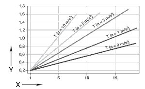
X = Load capacity[kg]
Y = drive torque [Nm]
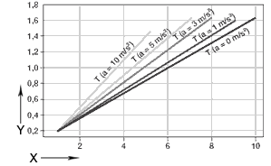
X = Load capacity[kg]
Y = drive torque [Nm]
Installation position horizontal - ZLW-1040, standard version 02
Installation position vertical - ZLW-1040, standard version 02
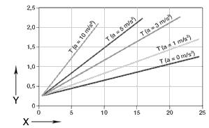
X = Load capacity[kg]
Y = drive torque [Nm]

X = Load capacity[kg]
Y = drive torque [Nm]
* Supposition: The moving mass is located in a circumscribed circle with a max. R = 100 mm to the middle of the rail, max. permissible torque, version 01: 1.3 Nm, a= 0 m/s² ; version 02: 2.4 Nm, a= 0 m/s²; constant drive without nominal value acceleration.
ZLW-0630 and ZLW-1040
ZLW-1040, basic version 02 and standard 02

X = load of the carriage [N]
Y = speed of the carriage [m/s]
The diagram accounts for the sum of all forces active on the carriage. ED = On-time
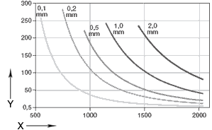
X = Support lenght [mm]
Y = load [N]
Sag permissible up to maximum 2 mm .
Drive torque and load of the ZLW-0630
Installation position horizontal - ZLW-0630, basic version 02
Installation position vertical - ZLW-0630, basic version 02
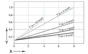
X = Load capacity[kg]
Y = drive torque [Nm]

X = Load capacity[kg]
Y = drive torque [Nm]
Installation position horizontal - ZLW-0630, standard version 02
Installation position vertical - ZLW-0630, standard version 02

X = Load capacity[kg]
Y = drive torque [Nm]

X = Load capacity[kg]
Y = drive torque [Nm]
* Supposition: The mass to be moved is in a circumscribed circle with a max. R = 100 mm to the centre of the guide rail, max. permitted torque, version 01: 1.3 Nm, a= 0 m/s² ; version 02: 2.4 Nm, a= 0 m/s²; constant drive without nominal value acceleration.
ZLW-0630 and ZLW-1040
ZLW-0630, basic version 02 and standard 02

X = load of the carriage [N]
Y = speed of the carriage [m/s]
The diagram accounts for the sum of all forces active on the carriage. ED = On-time
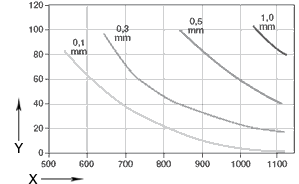
X = Support lenght [mm]
Y = load [N]
Sag permissible up to maximum 2 mm .
More than 100,000 products available! Delivery and consultation Mon-Fri from 7am-8pm and Sat from 8am-12pm!