Thread the locking ring approx. half-way onto the support nut 1. using torsion spring 2., and secure the spring tab in the bore.
DryLin® - Trapezoidal leadscrew nut - Technical data
drylin® lead screw units operate completely maintenance and lubricant-free on a variety of lead screw materials
because the nuts are made from iglidur® high-performance
polymers. In comparison to nuts with maintenance and lubrication requirements, these lead screw nuts provide significant advantages, especially in applications with high dust and dirt exposure (textile, rock and wood processing machinery) and in applications that include cleaning processes (packaging and foodstuff machinery).
drylin® lead screw nuts are designed to absorb axial forces. Any radial forces that may occur in the application should be absorbed by additional linear guides.
drylin® lead screw nuts, which are manufactured from maintenance-free iglidur® materials, are principally suited for use in temperatures ranging from –20 °C to +90 °C (150 °C, depending on material). However, please note that the temperature expansion causes a change in the maximum allowable load in addition to the changing clearance situation. When the application is exposed to particularly low or high temperatures and high loads, we recommend testing the suitability of the lead screw nuts for the specific case by means of empirical experiments. We have lead screw nuts available in various play classes to provide for their use in all temperature ranges.
For applications in humid environments, especially in wet area, the trapezoidal leadscrew nuts made of iglidur® J or iglidur® A180 should be used. These materials are characterized by very low moisture absorption.
iglidur® J
iglidur® A180
drylin® lead screw units feature completely dry-running travel by exclusively using maintenance-free iglidur® materials for lead screw nut production. Adhesion of soft particles such as dust and fibers is greatly reduced by deliberately eliminating lubricants. As compared to conventional, lubricated materials, it is common to see significant improvements in the service life in contaminated environments. However, the lead screw should be covered in environments with significant contamination and hard particles, such as metal chips or granite dust.
Noise can generally occur with the use of gliding lead screw units. In particular, long lead screws and long travels can cause self-induced vibrations in gliding systems. Due to their good gliding characteristics, lead screw nuts made from tribologically optimized iglidur® materials tend to develop much less noise than conventional plastics or metallic materials, such as bronze or brass. If your gliding lead screw unit develops noise, please contact us to discuss this with our experts.
drylin® lead screw units are manufactured in accordance with DIN 103. The testing takes place by means of standardized thread plug gage after production. For thread sizes that are not listed in the standard table, DIN 103 is converted to the corresponding size. The hygroscopic and thermal properties of the material are to be considered in the selection. Dimension changes can occur through moisture and/or heat at the usage site. For these reasons, a general DIN-compatibility cannot be guaranteed.
The functionality of gliding lead screw units requires a basic amount of play. Application specific parameters must be observed in addition to the lead screw unit clearance caused by manufacturing tolerances. In addition to thermal and hygroscopic environmental influences, the minimum clearance to be accounted for in the application must also take into account the friction heat generated by the application. The use of gliding lead screw units is therefore not recommended for precision drives without conducting functionality tests. In practice, pre-tensioning has proven to be an effective counter-measure for undesirable clearance. In addition to the solutions from our standard product range, our experts will gladly advise you about other measures.
Efficiency is defined as the ratio of output power to input power. drylin® lead screw nuts are characterized by low friction values and the resulting high efficiencies. Single start trapezoidal lead screw nuts achieve efficiencies between 20 and 48% under dry-running conditions. High helix lead screw nuts achieve efficiencies between 50 and 80% under dry running conditions. Although drylin® lead screw nuts were developed for completely dry running conditions, lubrication can help to additionally increase efficiency.
Single start trapezoidal lead screw units are self-locking. This means that the flank angle and the sliding friction prevent movement of the nut or the lead screw without the application of outside forces. As soon as the static friction is exceeded, the components are no longer self-locking. Multi-start trapezoidal lead screw units have a "residual self-locking" feature; high helix lead screw units are not self-locking.
Backlash refers to the clearance at direction reversal, which is caused in a lead screw unit by the axial clearance. Oscillations and self-induced vibrations (frequently the causes of noise, especially with long lead screws and high RPMs) are significantly reduced by means of radial pre-tensioning using a spring-elastomer.
Screw drives with steep thread for quick adjustments of small loads. The zero-backlash system ensures minimal backlash for life. Ideal for precise positioning and feed movements in medical, laboratory and printing engineering and other life-science fields. High-helix nuts without zero-backlash feature or trapezoidal thread should be used for high loads, dirt exposure or extreme external influences.

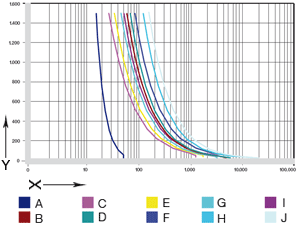
Y = Wear [Wt.-%]
A = POM
B = PA
C = J
D = W300
Fig. 01: Wear test on a rolled trapezoidal lead screw
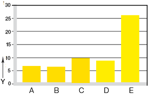
Y = Wear [mg/km]
A = J
B = W300
C = J350
D = A180
E = POM
Fig. 02: Wear test on a C15 lead screw [mg/km] stroke 140 mm, 50 N, lead screw C15 rolled, 450 RPM
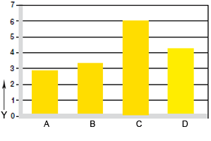
Y = Wear [mg/km]
A = J
B = W300
C = J350
D = A180
Fig. 03: Wear test on a stainless steel lead screw [mg/km] stroke 140 mm, 50 N, stainless steel lead screw, rolled, 450 RPM
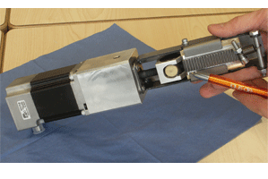
Anti-backlash lead screw nuts in a glue application system of a seam gluing machine (wood industry). These ensure the utmost in precision for the clearance-free adjustment mechanism.
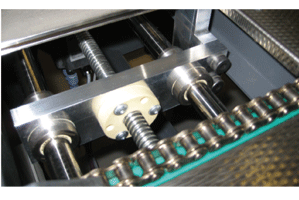
Format adjustment in the paper industry with anti-backlash lead screw nut
drylin® lead screw nuts must be secured against twisting and axial sway.
A maximum tightening torque of 2.5 Nm applies to M6 mounting screws on flanged nuts. We recommend the securing of the mounting screws via a third medium (e.g. liquid screw locking). The use of metallic press-fit sleeves is recommended for higher tightening torques.
1. Support nut
2. Locking ring with torsion spring
3. Friction disc
4. Axial element
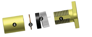

Position the friction disc 3. and the axial element 4. flush against the locking ring. Ensure that the locking ring does not rotate.

You can now let go of the locking ring, therefore pre-tensioning the nut on the lead screw.
The outside diameter of the cylindrical lead screw nuts has h9 tolerance. We therefore recommend a positive fit, e.g. by employing keyways for a secure lock. When low forces are involved, field experience has also demonstrated that screw connections will work. Gluing lead screw nuts is principally not recommended. However, if lead screw nuts are nevertheless intended for gluing, suitable tests need to be performed under all circumstances.

Thread the locking ring to the end of the support nut to tension the torsion spring.

Press together the support nut 1. and the axial element 4. and thread the lead screw through the nut. Pre-tension the locking ring while doing so.

The ultilzability and the operating behavior of the system also depend decisively on the spindles as counter-direction partners. Basically we recommend the purchase of nut and spindle as one system from a single supplier. Spindles are tested with ring gages compatible with DIN 103. Basically the drylin® trapezoidal leadscrew nuts can be used in combination with spindles made of steel, stainless steel or hard-anodized aluminum. "Split" lead screws (right and left-handed threads on one lead screw) are available in addition to right-handed and left-handed versions.
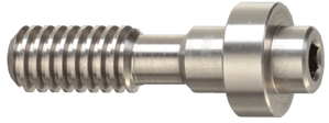
Take advantage of our machining service - we manufacture ready to install lead screws based on your needs. Please send us your drawing. We will promptly submit a quote.
Take advantage of our machining service - we manufacture lead screws nuts based on your needs. Please send us your drawing. We will promptly submit a quote.
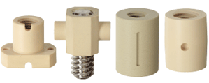
Custom nut examples
Standard drylin® lead screw nuts are available in 4 materials:
iglidur® J
This material is characterized by the best friction values with the most counter partners and low moisture absorption.
iglidur® W300
This material features high static strength.
iglidur® A180
This material meets the requirements of the FOOD AND DRUG ADMINISTRATION (FDA) and can therefore be used in direct contact with foods and pharmaceuticals.
iglidur® J350
This material features very high resistance to temperatures. Lead screw nuts made from iglidur J350 can be used up to 150 °C.
drylin® lead screw nuts are made from tribologically optimized materials. Already during the development phase, the focus is on optimizing the friction properties of the drylin® lead screw units, with the objective of attaining the lowest possible wear rates and good friction values. The igus® test lab in Cologne conducts several hundred tests every year on lead screw test fixtures in order to make the best possible service life and wear-resistance projections. Our experts will also gladly test your application.
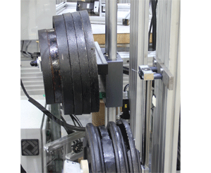
Test fixture at the igus® lab to determine service life
| iglidur® material | surface pressure |
|---|---|
| iglidur® J | 4 MPa |
| iglidur® W300 | 5 MPa |
| iglidur® A180 | 3,5 MPa |
| iglidur® J350 | 2 MPa |
The load capacity of the trapezoidal leadscrew nuts made of high-performance polymers is dependent on the surface pressure, the surface speed and the resultant temperature. The temperature behavior is additionally influenced by the duty cycle as well as the selected spindle material and its specific heat conductivity.
| iglidur® material | rotating long-term |
|---|---|
| iglidur® J | 1,5 |
| iglidur® W300 | 1,0 |
| iglidur® A180 | 0,8 |
| iglidur® J350 | 1,3 |
Max. allowable pv value
The permitted surface speed and the resultant feed rate for every thread size can be determined with the p x v value and the percentages of the surface contact area stated in the dimensions table.
| Duty cycle ED | pv-valuemax.[MPaxm/s] |
|---|---|
| 100 % | 0,08 |
| 50 % | 0,2 |
| 10 % | 0,4 |
Required percentage of surface contact area:
Ae = Faxial / ptol [mm2]
Selection of the required thread size and determination of the actual surface pressure:
preal = Faxial / Ae real [MPa]
pv-value:
pv = preal x v
Sliding speed:
v = n x d1 x π/ 60.000[m/s]
Number of revolutions:
n = v x 1.000 x 60 / π x d1 [1/min]
Feed rate:
s = n x P / 60.000 [m/s]
Drive torque:
Mta= Faxial x p / 2000 x π x η
Mte= Faxial x p x η/ 2000 x π
Fig. 05: Formula chart - lead screw units
| Faxial | Axial force |
| Pper | Max. permitted surface pressure 5 N/mm2 |
| preal | Actually occurring surface pressure for selected installation size |
| Ae real | Percentage of surface contact area of the selected trapezoidal leadscrew nut |
| P | Lead |
| d1 | Pitch diameter |
| Mta | Drive torque [Nm] when converting a rotating motion into a linear motion |
| Mte | Drive torque [Nm] when converting a linear motion into a rotating motion |
| v | Sliding speed [m/s] |
| s | Feed [m/s] |
| n | Number of revolutions [min-1] |
| η | Efficiency |
More than 100,000 products available! Delivery and consultation Mon-Fri from 7am-8pm and Sat from 8am-12pm!

