iglidur® - Surface speed
| Materials | Rotating | oscillating | Linear |
| Standards | |||
|---|---|---|---|
| iglidur® G | 1 | 0,7 | 4 |
| iglidur® J | 1,5 | 1,1 | 8 |
| iglidur® M250 | 0,8 | 0,6 | 2,5 |
| iglidur® W300 | 1 | 0,7 | 4 |
| iglidur® X | 1,5 | 1,1 | 5 |
| More all-rounder | |||
| iglidur® K | 1 | 0,7 | 3 |
| iglidur® P | 1 | 0,7 | 3 |
| iglidur® GLW | 0,8 | 0,6 | 2,5 |
| The endurance runner | |||
| iglidur® J260 | 1 | 0,7 | 3 |
| iglidur® J3 | 1,5 | 1,1 | 8 |
| iglidur® J350 | 1,3 | 1 | 4 |
| iglidur® L250 | 1 | 0,7 | 2 |
| iglidur® R | 0,8 | 0,6 | 3,5 |
| iglidur® D | 1,5 | 1,1 | 8 |
| iglidur® J200 | 1 | 0,7 | 10 |
| High temperatures | |||
| iglidur® V400 | 0,9 | 0,6 | 2 |
| iglidur® X6 | 1,5 | 1,1 | 5,4 |
| iglidur® Z | 1,5 | 1,1 | 5 |
| iglidur® UW500 | 0,8 | 0,6 | 2 |
| High media resistance | |||
| iglidur® H | 1 | 0,7 | 3 |
| iglidur® H1 | 2 | 1,0 | 5 |
| iglidur® H370 | 1,2 | 0,8 | 4 |
| iglidur® H2 | 0,9 | 0,6 | 2,5 |
| contact with food | |||
| iglidur® A180 | 0,8 | 0,6 | 3,5 |
| iglidur® A200 | 0,8 | 0,6 | 2 |
| iglidur® A350 | 1 | 0,8 | 2,5 |
| iglidur® A500 | 0,6 | 0,4 | 1 |
| iglidur® A290 | 1 | 0,7 | 3 |
| iglidur® T220 | 0,4 | 0,3 | 1 |
| Special applications | |||
| iglidur® F | 0,8 | 0,6 | 3 |
| iglidur® H4 | 1 | 0,7 | 1 |
| iglidur® Q | 1 | 0,7 | 5 |
| iglidur® UW | 0,5 | 0,4 | 2 |
| iglidur® B | 0,7 | 0,5 | 2 |
| iglidur® C | 1 | 0,7 | 2 |
Table 01: Surface speeds (short-term) of the iglidur® bearing in m/s
| Materials | Rotating | oscillating | Linear |
| Standards | |||
|---|---|---|---|
| iglidur® G | 2 | 1,4 | 5,3 |
| iglidur® J | 3 | 2,1 | 10 |
| iglidur® M250 | 2 | 1,4 | 5 |
| iglidur® W300 | 2,5 | 1,8 | 6 |
| iglidur® X | 3,5 | 2,5 | 10 |
| More all-rounder | |||
| iglidur® K | 2 | 1,4 | 4 |
| iglidur® P | 1,4 | 4 | |
| iglidur® GLW | 1 | 0,7 | 3 |
| The endurance runner | |||
| iglidur® J260 | 2 | 1,4 | 4 |
| iglidur® J3 | 3 | 2,1 | 10 |
| iglidur® J350 | 3 | 2,3 | 8 |
| iglidur® L250 | 1,5 | 1,1 | 3 |
| iglidur® R | 1,2 | 1 | 5 |
| iglidur® D | 3 | 2,1 | 10 |
| iglidur® J200 | 1,5 | 1,1 | 15 |
| High temperatures | |||
| iglidur® V400 | 1,3 | 0,9 | 3 |
| iglidur® X6 | 3,5 |
2,5 | 10 |
| iglidur® Z | 3,5 | 2,5 | 6 |
| iglidur® UW500 | 1,5 | 1,1 | 3 |
| High media resistance | |||
| iglidur® H | 1,5 | 1,1 | 4 |
| iglidur® H1 | 2,5 | 1,5 | 7 |
| iglidur® H370 | 1,5 | 1,1 | 5 |
| iglidur® H2 | 1 | 0,7 | 3 |
| contact with food | |||
| iglidur® A180 | 1,2 | 1 | 5 |
| iglidur® A200 | 1,5 | 1,1 | 3 |
| iglidur® A350 | 1,2 | 0,9 | 3 |
| iglidur® A500 | 1 | 0,7 | 2 |
| iglidur® A290 | 2 | 1,4 | 4 |
| iglidur® T220 | 1 | 0,7 | 2 |
| Special applications | |||
| iglidur® F | 1,5 | 1,1 | 5 |
| iglidur® H4 |
1,5 | 1,1 | 2 |
| iglidur® Q | 2 | 1,4 | 6 |
| iglidur® UW | 1,5 | 1,1 | 3 |
| iglidur® B | 1 | 0,7 | 3 |
| iglidur® C | 1,5 | 1,1 | 3 |
The peripheral speed is always significant in plain bearings. Crucial is not the absolute rotary speed, but the relative speed between the shaft and the bearing.

| d1 | Inner diameter of bearing [mm] |
| f | Frequency [s] |
| β | Angle [°] |
| n | Revolutions per minute |
iglidur® bearings have been developed for low to medium surface speeds in continuous operation.
Table 01 shows the permitted surface speeds of the iglidur® bearing for rotating, pivoting and linear motions.
These surface speeds are limit values under the assumed minimum pressure loads of the bearing.
In practice these limit values are not often reached due to the alternating effect of influences. Every increase of the pressure load inevitably leads to a lowering of the permitted surface speeds and vice versa.
The limit of the speeds is specified by the heating of the bearing. That is also the reason for the different speeds for the different types of motion.
In linear motions more heat can be conducted over the shaft, as the bearing uses a longer area on the shaft.
Considerations of the permitted surface speeds should always also include the wear resistance of the bearing. High surface speeds automatically bring in correspondingly high glide paths. With the surface speed, it thus increases not only the wear rate, but also the absolute wear in total.
The coefficient of friction of bearings in practice depends on the surface speed. High surface speeds results in a higher coefficient of friction than low speeds. Figure 08 illustrates this connection in the example of a steel shaft (Cf53) with a load of 0.7 MPa.
'))

Picture 01: Wear and friction tests with the example of an igubal® pillow block bearing
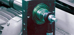
Picture 02: Determination of the maximum surface speeds of an igubal® rod end bearing at high rotational and surface speeds (shaft Cf53, rotary)
More than 100,000 products available! Delivery and consultation Mon-Fri from 7am-8pm and Sat from 8am-12pm!