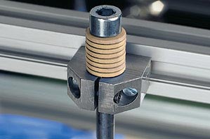
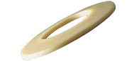
Polysorb Disk springs made of plastics
disc springs are annulus discs stressable in the axial direction, which are turned over in the shape of a disc in the axial direction. disc springs provide a more favorable space usage than other spring types. They are particularly suitable for designs that demand a small spring deflection.
+
When not to use Polysorb Disk springs?
For the implementation of specially flat load deflection curves that are possible with metal only with considerable complexity and expenditure (slotted versions).
For compensation of axial clearance and manufacturing tolerances
For vibration compensation
For noise dampening
When an antimagnetic material is required
For electrical and thermal insulation
When no corrosion problems should arise
When lubrication is not necessary
For low weight
For low space requirement
–
When not to use polyserb disk springs?
When constant spring forces are necessary over a wide temperature range
When high spring forces are required
The spring deflection of the disk spring is relatively small. Therefore a number of disk springs are combined in practice. Alternatively layered disk springs enhance the spring deflection in proportion to the number, whereby the overall spring force is as large as the force of the individual disk spring. To increase the force, the disk springs can be layered in parallel as a spring packet.
Chemical resistance
Polysorb disk springs are resistant to many chemicals.
iglidur® A500 has a higher resistance than iglidur® J.
| Medium | Resistance | |
| iglidur® J | iglidur® A500 | |
| Alcohols | + | + |
| Hydrocarbons | + | + |
| Fats, oils without additives | + | + |
| Fuels | + | + |
| Diluted acids | 0 to - | + |
| Strong acids | - | + |
| Diluted bases | + | + |
| Strong bases | + to 0 | + |
Humidity absorption
The low humidity absorption allows them to be used in wet or humid environment.
Polysorb® disk springs absorb humidity. Thereby their mechanical properties alter. In the worst application that can be thought of - extremely long application in water - Polysorb® disk springs still exhibit high spring force.
| iglidur® | Standard environment | saturated in water |
| J | 18 | 15 |
| A500 | 24 | 23 |
Increased operating temperature
Increased temperatures lead to the decline of stiffening in polymers. Polysorb® disk springs exhibit a maximum spring force of 8 N even at the maximum permitted temperature of 80° C. See figure for relationship of spring force to ambient temperature.
Polysorb Disk springs long-term tests
X = downward deflection [%]
Y= spring force [N]
A = JTEM-10
B = A500TEM-10
Figure 35.1: Spring force depending on the percentage of deflection measured in installation size 10
X= Ambient temperature [°C]
Y= Maximum spring force [N]
Figure 35.2: Influence of the ambient temperature on the spring force, measured on JTEM-10
Dimensions according to DIN 2093
|
Part No.: |
|
| De [mm]: | |
| Di [mm]: | |
| Part-No.* | Standard values: Spring deflections and spring forces | |||||||||||||
|---|---|---|---|---|---|---|---|---|---|---|---|---|---|---|
| De | Di | t | h0 | S0,25 | F0,25 | S0,5 | F0,5 | S0,75 | F0,75 | F1,0 | M | |||
| [mm] | [mm] | [mm] | [mm] | [mm] | [N] | [mm] | [N] | [mm] | [N] | [N] | [g] | |||
 JTEM-05 JTEM-05 |
10 | 5.2 | 0.5 | 0.25 | 0.06 | 1 | 0.13 | 2.4 | 0.19 | 3.6 | 5 | 0.04 | 2.33 USD |  |
| JTEM-06 |
12.5 | 6.2 | 0.7 | 0.3 | 0.08 | 3 | 0.15 | 5.1 | 0.23 | 8 | 12 | 0.11 | 2.05 USD | |
| JTEM-08 |
16 | 8.2 | 0.9 | 0.35 | 0.09 | 4 | 0.18 | 8 | 0.28 | 11 | 12 | 0.2 | 2.53 USD | |
| JTEM-10 |
20 | 10.2 | 1.1 | 0.45 | 0.11 | 5 | 0.22 | 10 | 0.33 | 15 | 18 | 0.33 | 2.94 USD | |
| JTEM-12 |
25 | 12.2 | 1.5 | 0.55 | 0.14 | 9 | 0.28 | 18 | 0.42 | 27 | 35 | 0.85 | 3.50 USD | |
| JTEM-16 |
31.5 | 16.3 | 1.75 | 0.7 | 0.18 | 15 | 0.35 | 32 | 0.53 | 51 | 70 | 1.44 | 4.15 USD | |
| JTEM-20 |
40 | 20.4 | 2.25 | 0.9 | 0.23 | 35 | 0.45 | 70 | 0.68 | 110 | 140 | 3.1 | 5.16 USD | |
| A500TEM-05 |
10 | 5.2 | 0.5 | 0.25 | 0.06 | 1 | 0.13 | 2.4 | 0.19 | 3.6 | 5 | 0.04 | Upon request | |
| A500TEM-06 |
12.5 | 6.2 | 0.7 | 0.3 | 0.08 | 3 | 0.15 | 5.1 | 0.23 | 8 | 12 | 0.11 | Upon request | |
| A500TEM-08 |
16 | 8.2 | 0.9 | 0.35 | 0.09 | 4 | 0.18 | 8 | 0.28 | 11 | 12 | 0.2 | Upon request | |
| A500TEM-10 |
20 | 10.2 | 1.1 | 0.45 | 0.11 | 5 | 0.22 | 10 | 0.33 | 15 | 18 | 0.33 | Upon request | |
| A500TEM-12 |
25 | 12.2 | 1.5 | 0.55 | 0.14 | 9 | 0.28 | 18 | 0.42 | 27 | 35 | 0.85 | Upon request | |
| A500TEM-16 |
31.5 | 16.3 | 1.75 | 0.7 | 0.18 | 15 | 0.35 | 32 | 0.53 | 51 | 70 | 1.44 | Upon request | |
| A500TEM-20 |
40 | 20.4 | 2.25 | 0.9 | 0.23 | 35 | 0.45 | 70 | 0.68 | 110 | 140 | 3.1 | Upon request | |
| More about selected part: | ||||||||||||||
3D-CAD Sample request
PDF
Quote request
Price list
myCatalog
Sample request
PDF
Quote request
Price list
myCatalog
|
||||||||||||||
* Material: iglidur® J, JTEM, Standard, iglidur® A500, A500TEM, high temperature resistance
Formula symbol, description and units:
| F | = Force |
| S | = Spring deflection |
| De | = Outer diameter [mm] |
| Di | = Inner diameter [mm] |
| t | = Thickness of the single disc [mm] |
| h0 | = Maximum downward deflection of spring [mm] |
| S0,25 | = 25% of the maximum downward deflection [mm] |
| F0,25 | = Spring force with 25% downward deflection [N] |
| S0,5 | = 50% of the maximum downward deflection [mm] |
| F0,5 | = Spring force with 50% downward deflection [N] |
| S0,75 | = 75% of the maximum downward deflection [mm] |
| F0,75 | = Spring force with 75% downward deflection [N] |
| F1,0 | = Spring force with 100% downward deflection [N] |
| M | = Weight of a single disc [g] |
More than 100,000 products available! Delivery and consultation Mon-Fri from 7am-8pm and Sat from 8am-12pm!