iglidur® clip bearings
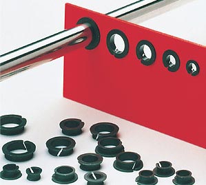
iglidur® clip bearings are especially intended for the shaft bushing through plates. For this reason the bearing has a flange on each of the two front sides. After the clip-on the bearings are secured on both sides in the plate.
The clip bearings have chamfered slot on the side that enables the mounting of the bearing on one side. After the mounting the bearing straddles and lines the bore in the plate. The shaft prevents the clip bearing from slipping out of the bore. The bearing cannot slip out of the bore even in axial movements.
Extremely simple mounting through lateral slot
Maintenance-free and self-lubricating
Good flexibility in punch hole
Good abrasion resistance
Quiet operation
Suitable for rotary and linear movements
Extendibility through the slot
Undetachable through double flange
Special dimensions possible
Plate thicknesses from 3 mm to 4 mm available from stock
Material: iglidur® M250
Special properties of the iglidur® clip bearings
iglidur® clip bearings are made from the most abrasion-resistant material, iglidur® M250. iglidur® M250 is a bearing material for rugged, wear-resistant bearing systems for medium loads. The bearings are self-lubricating and can be used dry. If required the bearings can also be lubricated. The material iglidur® M250 is resistant to all common lubricants.
The iglidur® clip bearings are the ideal solution for bearing functions with low loads. The easy mounting makes it ideal for applications with difficult bearing locations.
Compressive strength
The permitted static surface pressure of iglidur® M250 amounts to 20 MPa at room temperature. Due to the good adaptability to uneven surfaces of the bearing housing, a high pressure load capacity of the clip bearings persists even in punched holes. For the most small bearing surfaces, the good vibration dampening properties and the insensitivity to misalignment are of primary importance.
Surface speeds
Clip bearings are particularly wear resistant in slow rotating, oscillating and axial motions. You can find the maximum gliding speeds for the various motions for the iglidur® M250 material under the materials data link shown below. A lubrication at installation or continuous lubrication raises the permitted surface speeds.
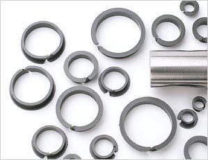
Clip bearings are available from stock in dimensions of 3 to 25 mm.
Fixation
For mounting, the bearings are laterally pressed together with the large flange. The chamfered slot makes the bearing spiral-shaped, whereby it can be easily inserted in the plate. The remaining slot in the attached clip bearing can compensate for linear expansions of the circumference. Thus narrow bearing clearances are possible with clip bearings. The bearing clearance is dimensioned in such a way that in a housing bore with a nominal diameter, a shaft made with the same nominal diameter turns easily. The clip bearing can be used in H-tolerance housings up to H13. The turning of the clip bearing in the bore is also permitted.
Operating temperatures
The wear resistance of the iglidur® clip bearings are excellent with operating temperatures till 80°C. Even at low temperature the bearings remain elastic and abrasion resistant.
When to use it?
When a sheet metal feedthrough is required
When the bearing should be captively clipped on in a drill hole with rough tolerance
For rotating, linear and pivoting movements
When a quick-mounting bearing solution is sought
When not to use it?
When constant temperatures of more than +80°C occur
iglidur® G
When a high-precision bearing is needed
iglidur® J
When the housing bore is more than 4 mm long
iglidur® Clips 2
iglidur® MKM
When very high surface pressures occur
iglidur® G

|
Part No.: |
|
| d1 [mm]: | |
Dimensions [mm]
| Order number | d1 | d2 | d3 | d4 | s | b1 | ||
|---|---|---|---|---|---|---|---|---|
| D11 * | -0,10 | +0,20 | ||||||
 MCM-03-02 MCM-03-02 |
3 | 4,2 | 4,8 | 6 | 0.6 | 3.2 | 1.53 USD |  |
| MCM-03-03 |
3 | 4,2 | 4,8 | 6 | 0.6 | 4.2 | 1.54 USD | |
| MCM-04-02 |
4 | 5,2 | 5,9 | 7 | 0.6 | 3.2 | 1.55 USD | |
| MCM-04-03 |
4 | 5,2 | 5,9 | 7 | 0.6 | 4.2 | 1.56 USD | |
| MCM-05-02 |
5 | 6,2 | 6,8 | 8 | 0.6 | 3.2 | 1.57 USD | |
| MCM-05-03 |
5 | 6,2 | 6,8 | 8 | 0.6 | 4.2 | 1.58 USD | |
 MCM-06-015 MCM-06-015 |
6 | 7,2 | 7,8 | 11 | 0.6 | 2.7 | Upon request | |
| MCM-06-02 |
6 | 7,2 | 7,8 | 11 | 0.6 | 3.2 | 0.90 USD | |
| MCM-06-03 |
6 | 7,2 | 7,8 | 11 | 0.6 | 4.2 | 0.99 USD | |
| MCM-06-04 |
6 | 7,2 | 7,8 | 11 | 0.6 | 5.2 | Upon request | |
| MCM-07-03 |
7 | 9 | 9,8 | 13 | 0.8 | 4.6 | Upon request | |
| MCM-08-02 |
8 | 9,6 | 10,4 | 13 | 0.8 | 3.6 | 0.89 USD | |
| MCM-08-03 |
8 | 9,6 | 10,4 | 13 | 0.8 | 4.6 | 1.08 USD | |
| MCM-08-04 |
8 | 9,6 | 13 | 10,4 | 0.8 | 5.6 | Upon request | |
| MCM-09-02 |
9 | 10,6 | 11,4 | 14 | 0.8 | 3.6 | 1.62 USD | |
| MCM-10-02 |
10 | 11,6 | 12,4 | 15 | 0.8 | 3.6 | 1.63 USD | |
| MCM-10-025 |
10 | 11,6 | 12,4 | 15 | 0.8 | 4.1 | Upon request | |
| MCM-10-03 |
10 | 11,6 | 12,4 | 15 | 0.8 | 4.6 | 1.64 USD | |
| MCM-10-08 |
10 | 11,6 | 12,4 | 15 | 0.8 | 9.6 | Upon request | |
| MCM-12-02 |
12 | 13,6 | 14,4 | 17 | 0.8 | 3.6 | 1.65 USD | |
| MCM-12-025 |
12 | 13,6 | 14,4 | 17 | 0.8 | 4.4 | Upon request | |
| MCM-12-03 |
12 | 13,6 | 14,4 | 17 | 0.8 | 4.6 | 1.66 USD | |
| MCM-12-035 |
12 | 13,6 | 14,4 | 17 | 0.8 | 5.1 | Upon request | |
| MCM-12-04 |
12 | 13,6 | 14,4 | 17 | 0.8 | 5.6 | 1.59 USD | |
| MCM-12-045 |
12 | 13,6 | 14,4 | 17 | 0.8 | 6.4 | Upon request | |
| MCM-14-03 |
14 | 15,6 | 16,4 | 19 | 0.8 | 4.6 | 1.43 USD | |
| MCM-16-02 |
16 | 17,6 | 18,4 | 21 | 0.8 | 3.6 | Upon request | |
| MCM-16-03 |
16 | 17,6 | 18,4 | 21 | 0.8 | 4.6 | 1.75 USD | |
| MCM-18-02 |
18 | 20 | 21 | 21 | 0.8 | 4 | Upon request | |
| MCM-18-03 |
18 | 20 | 21 | 23 | 1 | 5 | Upon request | |
| MCM-20-03 |
20 | 22 | 23 | 25 | 1 | 5 | 1.95 USD | |
| MCM-25-03 |
25 | 27 | 28 | 30 | 1 | 5 | 2.44 USD | |
| MCM-25-06 |
25 | 27 | 28 | 30 | 1 | 8 | Upon request | |
| More about selected part: | ||||||||
3D-CAD Sample request
PDF
Quote request
Price list
myCatalog
Sample request
PDF
Quote request
Price list
myCatalog
|
||||||||
iglidur® clip bearing, inch
|
Part No.: |
|
| d1 [inch]: | |
Dimensions in inches
| Part Number | d1 | d2 | d3 | d4 | s | b1 | ||
|---|---|---|---|---|---|---|---|---|
| D11* | -0,003 | +0,008 | ||||||
| MCI-03-01 |
3/16 | 0,2343 | 1/4 | 5/16 | 0.032 | 0,1380 | 1.55 USD | |
| MCI-04-01 |
1/4 | 0,3125 | 11/32 | 7/16 | 0.032 | 0,1380 | 1.57 USD | |
| MCI-05-01 |
5/16 | 0,3750 | 13/32 | 1/2 | 0.032 | 0,1380 | 1.59 USD | |
| MCI-06-01 |
3/8 | 0,4375 | 15/32 | 9/16 | 0.032 | 0,1380 | 1.61 USD | |
| MCI-07-01 |
7/16 | 0,5000 | 17/32 | 5/8 | 0.032 | 0,1380 | 1.63 USD | |
| MCI-08-01 |
1/2 | 0,5625 | 19/32 | 11/16 | 0.032 | 0,1380 | 1.65 USD | |
| MCI-03-02 |
3/16 | 0,2343 | 1/4 | 5/16 | 0.032 | 0,2000 | 1.56 USD | |
| MCI-04-02 |
1/4 | 0,3125 | 11/32 | 7/16 | 0.032 | 0,2000 | 1.58 USD | |
| MCI-05-02 |
5/16 | 0,3750 | 13/32 | 1/2 | 0.032 | 0,2000 | 1.60 USD | |
| MCI-06-02 |
3/8 | 0,4375 | 15/32 | 9/16 | 0.032 | 0,2000 | 1.62 USD | |
| MCI-07-02 |
7/16 | 0,5000 | 17/32 | 5/8 | 0.032 | 0,2000 | 1.64 USD | |
| MCI-08-02 |
1/2 | 0,5625 | 19/32 | 11/16 | 0.032 | 0,2000 | 1.66 USD | |
| More about selected part: | ||||||||
|
3D-CAD
Sample request
PDF
Quote request
Price list
myCatalog
|
||||||||
More than 100,000 products available! Delivery and consultation Mon-Fri from 7am-8pm and Sat from 8am-12pm!